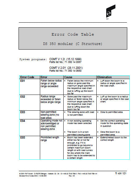
Error Code Table PAT Hirschmann DS350
- on June 29, 2022
- Categories: News
The PAT Hirschmann error codes listed in the error table explain the various faults, which can occur with the PAT DS350 Load Moment Indicator (LMI). Please Note that this is a generic list of PAT Hirschmann Error Codes. Different PAT DS 350 systems may have different error codes. Please contact the manufacturer if there is any uncertainty about the PAT Hirschmann Error Codes you receive.
PAT Hirschmann error codes affecting crane safety should only be repaired by trained service personnel, please contact the manufacturer if you need support for matters that are beyond your technical capabilities.
Download Printable Copy HERE
|
Error Code |
Error |
Cause |
Elimination |
|
E01 |
Fallen below radius range or angle range exceeded |
Fallen below the minimum radius or gone past the maximum angle specified in the respective load chart due to luffing up the boom too far |
Luff down the boom to a radius or angle specified in the load chart. |
|
E02 |
Radius range exceeded or fallen below angle range |
Gone past the maximum radius or fallen below the minimum angle specified in the respective load chart due to luffing down the boom too far |
Luff up the boom to a radius or angle specified in the load chart. |
|
E03 |
Non-permitted slewing zone (no load area) |
The slewing zone with load is not permitted |
Slew to permitted area |
|
E04 |
Operating mode not acknowledged or non permitted slewing zone |
A non existing operating mode has been selected |
Set the correct operating mode for the operating state in question |
|
The boom is in a non-permitted slewing zone |
Slew the boom to a permitted area |
||
|
E05 |
Prohibited length range |
Boom has been extended either too far or not far enough, e.g. if it is prohibited to go beyond a certain maximum boom length or with load curves for jibs where the main boom has to be extended to a certain length |
Extend/retract boom to the correct length |
|
|
|
Length sensor adjustment has changed, e.g. the cable slid off the length sensor reel |
Retract boom. Check the prestress of the cable reel (cable must be taut). Open the length sensor and carefully turn the length sensor pot counterclockwise until the detent by means of a screwdriver |
|
|
|
Clutch between length sensor pot and drive is defective |
Replace the complete clutch including drive wheel and adjust length sensor pot as described above |
|
|
|
Failure of +5V supply of analog part of analog board |
Check +5V supply. Exchange man board in case of voltage failure or breakdown when loaded with 50 ohm aprox. |
|
|
|
Cable between central unit and length sensor is defective or disconnected |
Check cable and plugs, replace, if need be |
|
|
|
Defective length potentiometer |
Replace length potentiometer |
|
E06 |
Radius range exceeded or fallen below angle range with luffing jib operation |
Maximum radius as specified in the load chart exceeded or fallen below minimum angle due to luffing down the luffing jib too far |
Luff the jib to a radius or angle specified in the load chart. |
|
E07 |
Faulty acknowledgment of the overload relay on the connection board. The relay should be energized, the 2nd contact however is indicated to be off, or the 2nd contact is indicated to be on while the relay should be de- energized. |
Overload relay or connection board are defective |
Replace connection board |
|
|
|
Processor board defective |
Replace processor board |
|
E08 |
No acknowledgment from the anti-two- block relay |
refer to E07 |
refer to E07 |
|
E10 |
Error in the length measurement |
With the boom retracted, the signal "main boom length" differs by more than 2 % from the programmed value for the basic length |
Check length sensor of the main boom |
|
With the boom retracted, the signal "length Tele I (+II)" differs by more than 2 % from the reference value 0 |
Check length sensor 2. |
||
|
E11 |
Fallen below lower limit value for measuring channel "length main boom" |
Cable between central unit and length sensor is defective or disconnected. Water inside the plug of the length/angle sensor |
Check cables as well as plugs, replace, if need be |
|
Length potentiometer is defective |
Replace length potentiometer |
||
|
Electronic component in the measuring channel is defective |
Replace LMI main board or processor board |
||
|
E12 |
Fallen below the lower limit value in the measuring channel "pressure piston side" |
Cable between the central unit and pressure transducers defective or water inside the plugs |
Check cables as well as plugs, replace, if need be |
|
Pressure transducer is defective |
Replace pressure transducer |
||
|
Electronic component in the measuring channel is defective |
Replace LMI main board or processor board |
||
|
E13 |
Fallen below lower limit value in the measuring channel "pressure rod side" |
refer to E12 |
refer to E12 |
|
E14 |
Fallen below lower limit value in measuring channel "force" |
Cable between the central unit and pressure transducers defective or water inside the plugs
|
Check cable as well as plugs, replace, if need be. |
|
Force transducer defective |
Replace force transducer |
||
|
Electronic component in the measuring channel is defective |
Replace LMI main board or processor board |
||
|
E15 |
Fallen below lower limit value for the measuring channel “angle main boom”. |
Cable from central unit to the length/angle sensor defective or loose. Water inside the plug of the length/angle sensor |
Check cable as well as plugs, replace, if need be. |
|
Angle potentiometer defective |
Replace angle sensor |
||
|
Electronic component in the measuring channel is defective |
Replace LMI main board or processor board |
||
|
E16 |
Fallen below lower limit value for measuring channel “angle 2" |
Cable between the central unit and angle sensor defective or loose. Water inside the plug of the angle sensosr |
Check cable as well as plugs, replace, if need be |
|
Angle potentiometer defective |
Replace angle sensor |
||
|
Electronic component in the measuring channel is defective |
Replace LMI main board or processor board |
||
|
E17 |
Fallen below lower limit value "length telescope I (+II)" |
Cable between the central unit and length sensor defective or loose. Water inside the plug of the legth sensor |
Replace length sensor |
|
Length potentiometer is defective |
Replace length sensor |
||
|
Electronic component in the measuring channel is defective |
Replace LMI main board or processor board |
||
|
E18 |
Front outrigger overloaded |
Front outrigger overloaded |
|
|
E19 |
Reference and/or supply voltage defective |
The supply voltage is falsified by one of the sensors (DAV, LWG) |
Check the voltages on the LMI main board (AGND = MP0). Check sensors, plugs and cable, replace, if need be |
|
Electronic component is defective |
Replace LMI main board |
||
|
A/D converter defective |
Replace LMI main board |
||
|
E1A |
Fallen below lower limit value in measuring channel "slewing angle 1" |
Cable between the central unit and slew angle sensor defective or loose. Water inside the plug of the angle sensor |
Check cables as well as plugs, replace, if need be |
|
Slew angle potentiometer is defective |
Replace slewing angle sensor |
||
|
Electronic component in the measuring channel is defective |
Replace LMI main board or processor board |
||
|
E1B |
Fallen below lower limit value in measuring channel "slewing angle 2" |
refer to E1A |
refer to E1A |
|
E21 |
Upper limit value in measuring channel "main boom length" has been exceeded. |
refer to E11 |
refer to E11 |
|
E22 |
Upper limit value in measuring channel "pressure piston side" has been exceeded |
refer to E12 |
refer to E12 |
|
E23 |
Upper limit value in measuring channel "pressure rod side" has been exceeded. |
refer to E12 |
refer to E12 |
|
E24 |
Upper limit value in measuring channel "force" has been exceeded. |
refer to E14 |
refer to E14 |
|
E25 |
Upper limit value in measuring channel "main boom angle" has been exceeded. |
refer to E15 |
refer to E15 |
|
E26 |
Upper limit value in measuring channel "angle 2" has been exceeded. |
refer to E16 |
refer to E16 |
|
E27 |
Upper limit value in measuring channel "length telescope I (+II) has been exceeded. |
refer to E17 |
refer to E17 |
|
E29 |
Reference and/or supply voltage defective |
refer to E19 |
refer to E19 |
|
E2A |
Upper limit value in measuring channel "slewing angle 1" has been exceeded |
refer to E1A |
refer to E1A |
|
E2B |
Upper limit value in measuring channel "slewing angle 2" has been exceeded |
refer to E1A |
refer to E1A |
|
E31 |
Error in the system program |
The system program PROM is defective |
Replace the system program PROM (PROM No. 0) |
|
E38 |
System program and data EPROM do not match. |
The system program in the LMI does not match to the programming in the data EPROM |
Replace the system program PROM or the data EPROM (PROM No. 1) |
|
E39 |
System program and TLK EPROM do not match |
The system program in the LMI and the programming in the TLK EPROM do not match. |
Replace system program PROM or TLK EPROM (PROM No. 2). |
|
E41 |
Error in the internal write/read memory (RAM) of the computer component 80C537 |
Computer component 80C537 defective |
Replace computer component 80C537 |
|
CPU module defective |
Replace CPU module |
||
|
Processor board defective |
Replace processor board with CPU module |
||
|
E42 |
Error in the external write/read memory, 1st part (RAM) |
Write/read memory (CMOS RAM) or processor board defective |
Replace processor board with CPU module |
|
E43 |
Error in the external write/read memory, 2nd part (RAM) |
refer to E42 |
refer to E42 |
|
E45 |
Redundancy error in the A/D conversion |
The A/D converter on the processing board and the redundant A/D converter in the CPU 80C537 provide different results. |
Replace processor board. |
|
E46 |
Error in the A/D converter uPD 7004 of the processor board. |
No acknowledgment of the A/D converter uPD 7004 |
Replace processor board. |
|
E47 |
Error in the monitored write/ read memory. |
The CRC sign of the monitored write/read memory is wrong |
Restart the LMI |
|
The CRC verification of the monitored write/read memory provides an incoherent result |
The buffer battery is discharged (< 2V at 1kOhm). |
Replace buffer battery on the LMI main board |
|
|
Processor board defective. |
Replace processor board. |
||
|
E48 |
Cyclic RAM test: error in the internal write/read memory (RAM) of the computer component 80C537 |
Computer component 80C537 defective |
Replace computer component 80C537 |
|
CPU module defective |
Replace CPU module |
||
|
Processor board defective. |
Replace processor board with CPU module. |
||
|
E51 |
Error in the crane data EPROM or EEPROM. |
No valid data in the crane data EEPROM |
Load crane data EEPROM containing valid data |
|
Memory module wrongly bridged. |
Bridge memory module acc. to memory type |
||
|
Crane data EPROM defective |
Replace crane data EPROM |
||
|
E52 |
Error in load chart PROM. |
Memory module wrongly bridged |
Bridge memory module acc. to memory type |
|
Load chart EPROM defective. |
Replace load chart EPROM |
||
|
E56 |
Error in crane data EEPROM. |
Memory module wrongly bridged |
Bridge memory module acc. to memory type |
|
Crane data EEPROM defective |
Replace crane data EEPROM |
||
|
E57 |
Error in serial crane data EEPROM. |
Serial crane data EEPROM does not contain valid data |
Write data on the serial crane data EEPROM (by means of test program or on-line function), then restart the LMI |
|
Memory module defective |
Replace memory module. |
||
|
E58 |
Error in the serial analog data EEPROM. |
No valid data in the serial analog data EEPROM |
Write data on the serial analog data EEPROM by means of the test program, then, restart the LMI |
|
LMI main board defective. |
Replace LMI main board. |
||
|
E60 |
The number of the selected EPROM base and the programmed value are not identical |
Load chart EPROM defective. |
Replace load chart EPROM |
|
Base number not programmed |
Program the correct base number (1 for base 1, 2 for base 2) |
||
|
Load chart EPROM wrongly programmed |
Check base programming in the load chart EPROM |
||
|
E61 |
Error in the boom control extension. |
Cable between the central unit and the boom control extension defective. |
Check the cable to the boom control extension |
|
Profibus adapter in the central unit defective |
Replace the profibus adapter |
||
|
Profibus adapter in the • Boom control extension defective |
Replace the profibus adapter |
||
|
Boom control extension defective |
Replace the boom control extension |
||
|
E62 |
Error digital inputs 1-8 in the boom control extension |
Module for digital inputs in the Boom control extension defective |
Replace the module for the digital inputs |
|
Boom control extension defective |
Replace the boom control extension |
||
|
E63 |
Error digital inputs 9-16 in the boom control extension |
Module for digital inputs in • the Boom control extension defective |
Replace the module for the digital inputs |
|
Boom control extension defective |
Replace the boom control extension |
||
|
E64 |
Error analog output 1 in the boom control extension |
Module for analog output 1 in the Boom control extension defective |
Replace the module for the analog output 1 |
|
Boom control extension defective |
Replace the boom control extension |
||
|
E65 |
Error analog output 2 in the boom control extension |
Module for analog output 2 in the Boom control extension defective |
Replace the module for the analog output 2 |
|
Boom control extension defective |
Replace the boom control extension |
||
|
E66 |
Error analog outputs in the boom control extension. |
Module for analog outputs in the Boom control extension defective |
Replace the module for the analog outputs |
|
Boom control extension defective |
Replace the boom control extension |
||
|
E70 |
Error relay output module |
Module for relay outputs not • available or defective |
Install or replace the module for the relay outputs |
|
LMI main board is defective |
Replace LMI main board. |
||
|
E71 |
Faulty acknowledgment of digital output K1 on the output module Output should be energized but the status is signaled to be off or the status is signaled to be on whereas the output should be de- energized. |
Digital output K1 or output module defective |
Replace digital output module. |
|
LMI main board is defective |
Replace LMI main board. |
||
|
E72 ... E77 |
Faulty acknowledgment of outputs K2...K7 on the output module. |
refer to E71 |
refer to E71 |
|
E80 |
Error in the slewing angle measurement |
The difference between the average of the slewing angle and one of the wipers of the slewing potentiometer is out of the tolerance |
Check the slewing potentiometer adjustment. Replace the slewing potentiometer |
|
E84 |
Wrong rigging condition. |
The selected rigging condition is not contained in the data EPROM. |
Select another rigging condition. Check the programming in the data EPROM. |
|
E85 |
Error in the radius determination |
The computed radius is too small (negative deflection) |
Check the programming in the data EPROM. |
|
E86 |
Faulty percentage for at least one telescope |
Telescope has a percentage <-2%or>106%. |
Read out the percentages on the console. If a telescope has to be extended too far: retract tele and bolt |
|
Length measurement Tele I + II defective |
Check length measurement Tele I (see E17) |
||
|
Measurement of overall length defective |
Check length measurement (see E11) |
||
|
E89 |
Operating mode switchover with load. |
The operating mode on the console has been switched over with the boom loaded. |
Select operating mode without load on the boom |
|
E91 |
No data trans- mission from the console to the central unit |
24 V supply of the console is interrupted |
Check 24 V at terminal X1 of the console electronics |
|
Interruption or accidental ground in the line between console electronics and central unit |
Check the connection console electronics - central unit. In case of an accidental ground, the transmitter module of the console electronics might be damaged. Therefore, replaces the console electronics. |
||
|
Transmitter / receiver module is defective |
Exchange console electronics or LMI main board resp. |
||
|
E92 |
Error in the data transmission from console to central unit |
Loose connection in the line between console electronics and central unit |
Check the connection between console electronics and central unit |
|
Transmitter/receiver module is defective |
Exchange console electronics or LMI main board resp. |
||
|
E93 |
Error in the data transmission from the central unit to the console |
refer to E92 |
refer to E92 |
|
E94 |
No data transmission from the central unit to the console |
Interruption or accidental ground in the line central unit - console |
Check line to the console (in case of accidental ground, replace console electronics, too) |
|
5 V supply of the computer in the central unit is missing |
Check connection to the power unit |
||
|
5 V supply is too low |
Exchange the LMI main board |
||
|
Transmitter/receiver module is defective |
Replace console electronics or LMI main board |
||
|
Computer module is defective |
Replace processor board. |
||
|
Electro-magnetic interferences (e.g. when switching contactors or valves) |
Eliminate the source of interferences by inverse diodes or varistors |
||
|
E95 |
Error in the console EPROM |
The console EPROM is defective |
Replace the console EPROM |
|
E96 |
Error in the internal RAM of the console |
The CPU of the console is defective |
Replace the CPU of the console |
|
The console main board is defective |
Replace the console main board. |
||
|
E97 |
Error in the external RAM of the console |
The external RAM of the console is defective |
Replace the external RAM of the console. |
|
The console main board is defective. |
Replace the console main board. |
||
|
EAB |
Short circuit in the A2B switch circuit |
Short circuit in the A2B switch |
Replace A2B switch |
|
Short circuit in the cable to the A2B switch |
Replace cable to the A2B switch |
||
|
EB0 |
Free fall switch on |
Free fall monitoring |
DGA 9.4 = 0, DGA9.5 = 0 |
|
EB1 |
Free fall solenoid on |
Free fall monitoring |
DGA 9.4 = 0, DGA9.5 = 0 |
|
EB2 |
Free fall switch and solenoid on |
Free fall monitoring |
DGA 9.4 = 0, DGA9.5 = 0 |
|
EC0 |
Prohibited area |
Boom is about to collide with the engine hood, switch off |
Check values in the data prom DGA 11.5 |
|
EC1 |
Approaching prohibited area |
Boom is about to collide with the engine hood, prewarning |
Check values in the data prom DGA 11.5. |


