PAT Hirschmann Anti Two Block Wiring Circuit Diagram
- on July 13, 2021
- Categories: News
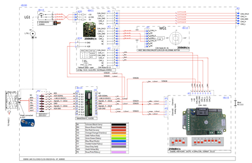
We have received a number of requests for assistance with A2B wiring diagrams and A2B wiring schematics for older PAT Hirschmann DS350 systems. This diagram is from the PAT DS350G/GW Service Manual P/N 031-300-190-046, Rev. B, 04/18/01.
Wiring schematics for the Anti Two Block switch (A2B Switch), 6 pin A2B receptacle as installed on cranes with jib anti two block systems, and the wiring through the LWG cable reel is included.
A PDF of the Anti Two Block Schematic can be found by clicking here
General Anti Two Block Information
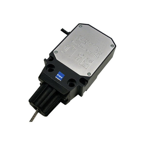
Anti-Two-Block Switch: The anti-two-block switch monitors the load block and its relationship with the head of the boom. In working condition the switch is closed. When the hook block strikes the weight the circuit opens, disengaging a relay output to the lock out solenoid valves, where applicable. To check the cable for damage, (short circuit to ground) there is a 4.7k resistor between ground and the contact of the switch, to give a signal back to the central unit. The weight at the anti-two-block switch keeps the switch closed until the hook block strikes it.
The Length-Angle Transducer: The length-angle sensor (LWG) is a combination of two transducers in one box, fitted at the base section of the boom. It measures the length and the angle of the boom. A reeling drum drives a potentiometer, which is the length transducer. Part of the length transducer circuit is the length cable on the drum, which is a two-conductor cable (screen and live). It is connected to the anti-two-block switch at the boom head and to a slip ring body in the LWG. The angle transducer is fitted in a small box filled with oil. A pendulum drives the axle of the angle potentiometer.


